Products
Products
Contact Us
BoZhong (Shandong) Industrial Equipment Co., Ltd. | Part of the Atlas Copco Group
Address: No.50# YiDa Road, NanDing Town, Economic Development Zone, ZiBo, ShanDong, China
Tel: +86-533-2530388
Website: en.zbbz.com
2BW series water ring vacuum pump closed loop system
Download the brochure of 2BW series (pdf)
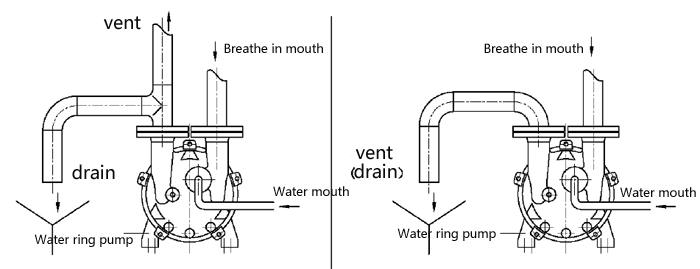
Summary: The water ring vacuum pumps are used widely in chemical and pharmacy areas for its characteristics of the work principle and structure. Normally, the operating liquid of the water ring vacuum pumps is almost discharged out directly or drained into the large circulation pool, as Figure 1.

Figure 1 Supply and discharge of operating liquid for normal water ring vacuum pump
Water ring vacuum pump to discharge water into a large circular pool or discharged directly. This way of water supply and drainage connection is convenient, simple to use, is mainly used in the practical application.
But to discharge the operating liquid out directly has some disadvantages as the following items while the pumped medium contains the organic solvent or poisonous substance.
.While the water ring vacuum pump works, the pumped gases and the operating water are mixed. So the discharged water contains a lot of solvent or poisonous substance. Further
the more the discharged water, the heavier pollution to the environment.
.The water containing the solvent or poisonous substance will set out a lot of harmful gases and increase the environment pollution.
. The pumped solvent is not easy to reclaim and that causes lots of waste
For these above reasons, more and more chemical and pharmacy enterprises choose to use the 2BW series package units.
Main characteristics of the liquid ring vacuum pump closed loop system:
1. to shorten the installation period of the customer to use the whole set of the system which includes the pump, separator, heat-exchanger, frame and pipeline etc.
2. to decrease the environment pollution efficiently while the working liquid is the various solvent.
3. If use the pumping medium as a working fluid, pumping medium by recycling.
4. the 2BW series vacuum system is non-standard products of our company, they are designed by the practice conditions of the inlet port, cooling water and discharge port etc.
|
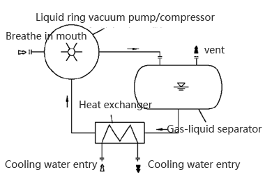
Working principle: The most basic 2BW series liquid ring vacuum pump / compressor closed loop system is shown in Figure 2: Composition of equipment:
The main components of the closed loop system of liquid ring vacuum pump / compressor are included: . Liquid ring vacuum pump / compressor . Gas-liquid separator . Heat exchanger . Common chassis . Internal pipeline |
 |
According to the actual situation, choose to install the following accessories:
1. The suction port vacuum check valve, to prevent vacuum pump / compressor down the back flow, generally needs to install the vacuum check valve or pneumatic valve at the entrance of the pump.
2. The suction port vacuum table or pressure sensor for easy observation of the pump suction port pressure, can be installed in the pump suction port vacuum table. If need to control action according to the suction pressure, should be installed in the pump suction port pressure sensor.
3. The suction port filter, such as the system and the pipeline, may have a foreign body into the pump, the pump should be installed in the suction port filter or filter.
4. The overflow port of the separator can be discharged from the gas-liquid separator.
5. The separator fluid inlet, such as insufficient working fluid can be appropriate to supplement working fluid from the fluid.
6. Separator liquid level meter can be observed in the separator liquid level, such as automatic control of liquid level, you should install the liquid level meter with signal output, automatic overflow or fluid replacement device.
7. The separator pressure gauge, such as the separator, may generate pressure; the pressure gauge should be installed on the separator.
8. If you need to observe the working fluid inlet temperature, the thermometer should be installed in the working fluid pipeline.
9. The working fluid booster pump, such as the working fluid of the pump supply is insufficient or working pipeline resistance is larger, can be installed working fluid booster pump.
10. Working fluid control valve, such as the working fluid supply may be too large to be installed in the working fluid pipeline control valve.
11. Cavitation protection pipeline, such as vacuum pump suction pressure close to the working fluid saturated vapor pressure, the vacuum pump should be installed between the vacuum pump and the protection of the pipeline.
12. Such as the use of the compressor, the compressor should be installed between the suction and exhaust pipe of the balance between the pipeline and the corresponding valve accessories.
13. Suction pipe, exhaust pipe, working fluid pipeline globe valve, such as liquid ring vacuum pump / compressor design for the parallel use of multiple pumps, common separator, should be in the suction line, exhaust pipe, working fluid pipeline installation of the valve.
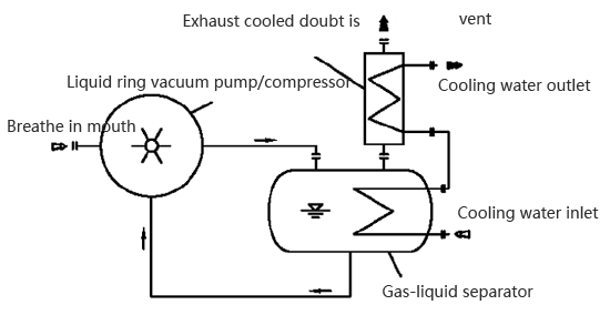
14. Exhaust gas condenser, such as the need for the exhaust port of the condensate gas for trapping or recycling, can be installed in the gas liquid separator exhaust port condenser.
15. If there are other special requirements, you can install the appropriate accessories
Basic type:
1. Working fluid using water or other liquid, the extraction of the media is not recycled.
Flow chart as shown in Figure 2
2. The working fluid is pumped through the medium, and the exhaust port increases the exhaust condenser.
Flow chart as shown in Figure 3
We have successfully applied the methanol and ethanol, ethylene glycol, toluene, xylene, acetone and acrylonitrile, dichloromethane, chloroform, carbon tetrachloride, etc. solvent as the liquid ring vacuum pump working fluid.

![]() Equipment selection considerations:
Equipment selection considerations:
Because the liquid ring vacuum pump / compressor selection should be calculated according to the detailed conditions, for our company to design selection, please be sure to provide detailed conditions. Fill in the sample company page 70 Annex: liquid ring vacuum pump / liquid ring compressor / liquid ring pump unit parameters table.
2BW series liquid ring vacuum pump closed loop system is 2BV or 2be series liquid ring vacuum pump and water separator, heat exchanger and all kinds of pipe accessories to change the composition of the complete sets of equipment. Compared to the single liquid ring vacuum pump, the installation is more convenient. Because of working fluid can recycling, the system greatly reduces the working fluid consumption and pollution to the environment. Therefore, in the pumping of toxic gas and smoke in gas containing organic solvents, and so on various occasions has obvious superiority. In most applications can be used liquid ring vacuum pump closed loop system.
Liquid ring vacuum pump closed loop system working fluid can be used in a variety of media: water, methanol, ethanol, xylene, aniline, acetone and other organic solvents, transformer oil, etc.

|
N1.2
|
Suction port |
N2.2
|
Discharge port |
N3.3
|
Operating liquid supplying port |
|
N4.2
|
Overflow port |
N4.6
|
Drain |
N5.0
|
Inlet of cooling liquid |
|
N6.0
|
Outlet of cooling liquid |
|
|
||
|
|
|
|
|||
|
010
|
Vacuum pump |
012
|
Pressure meter |
013
|
Valve |
|
030
|
Motor |
060.1
|
Coupling |
060.2
|
Protect cover |
|
080
|
Separator |
130
|
Heat exchanger |
140
|
Base plate |
|
160
|
Suction pipes |
163
|
No-return valve |
170
|
Discharge pipes |
|
230
|
Level meter |
242
|
Valve |
244
|
Valve |
|
246
|
Valve |
249
|
Valve |
260
|
Working liquid pipeline |
|
280
|
Working liquid pipeline |
360
|
Anchor bolt |
420
|
thermometer |
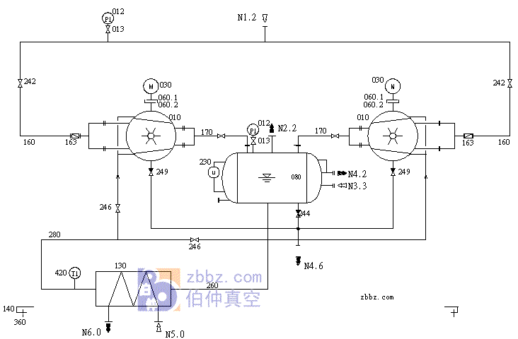
Flow chart of 2BW package unit (One works and another prepares)
Firstly, the gases are pumped from the inlet flange N1.2. Secondly, the gases is compressed and mixed with much operating liquid, and then the mixture passes the discharge pipes (170) and flows to the separator (080). Finally, the mixture is divided in the separator. The gases go out the system from the flange N2.2.
The separator (080) is designed with a level meter (230) which denotes the liquid level. The normal level is limited from the max. to the min.(determined by the visible scope of the level meter). If the level is lower, the liquid will be supplied through the port N3.3; if the level is higher, the liquid will be discharged from the overflow port 4.0. So the liquid level in the separator keeps a definite height by this method.
The discharge port N4.6 is used to drain the liquid in the separator (080) and vacuum pump (010) thoroughly.
The 2BW package unit is designed to make the two vacuum pumps (010) to use the same separator (080) and exchanger (130). (Note: while one pump works, the other prepares). When one pump works, the butterfly valves on the suction and discharge pipes of the other prepared pump must be shut off. In general, the unit is composed of one pump (010) and one separator (080) and one exchanger (130).
If you need liquid ring vacuum pump closed loop system type calculation, please fill in the parameter table (click to download),fax or mail us.


